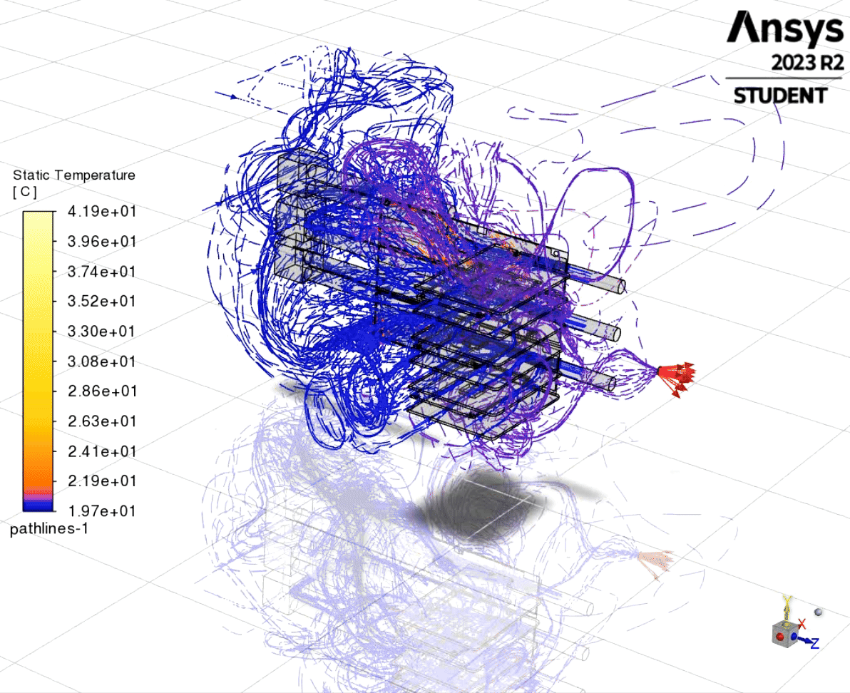
My most recent work in May of this year simulating the flow of compressed air in a volume with multiple electronic systems. The video below shows a brief look at the install of the hoses to keep all of our sensors cool to prevent accumulation of dew or overheating of the boards to capture near-infrared images of the night sky!
In my sophomore year I spent a lot of time working on hardware for the WINTER telescope as well. Specifically, I was tasked with designing a few camera mounts for the telescope as well as implementing a new translation stage with a finer adjustment step for finding focus. The telescope mount also had to have mobility about both the y and z axes.

The original camera design and rendering, the train, camera, mount, and clamps needed to be adjusted.

Final camera version with the inserted ASI294 MC Pro Cool camera.
One of the largest challenges of this project was designing a flexure mount, meant to bend under the force of a set screw to allow changes in the angle of the mount about the z axis. In order to come up with the preliminary design for this flexure mount, I CADed a basic form of the flexure mount and then performed calculations from a book of fine-adjustment mechanisms*. I was able to use the following equation below, which has been put in the ideal form to solve for the thickness of the joint (as opposed to the maximum moment).

Thickness equation where E is the young's modulus, b is the with of the part, theta is the bend angle, R is the radius, and M is the induced moment (below the yield strength of the set screw multiplied by the load distance).
Using this equation, I was able to set the thickness for different, materials, which you can see was inversely related to the young's modulus. This makes sense analytically as the young's modulus gives the ratio of stress to strain, so a material that strains less under a greater load would require a thinner cross section to bend under the same bending moment. Conducting Finite Element Analysis, we were able to determine, however, that the stress concentrations for 6061 T6 and 7075 aluminum would break the joint if bent to the four degrees as intended, leading us to make the component out of stainless steel.

Stress test on aluminum, which would not sufficiently bend and ended up yielding

Stress test done on titanium, still notwithstanding the forces as stainless steel does
Although significant modifications to the project are still required, the third iteration (my final contribution to the project before leaving following 7 months of work) is seen below.

*Eckhardt, Homer. Kinematic Design of Machines and Mechanisms. 1st ed. McGraw-Hill Professional, 1998.